Ceylan Türkyilmaz & Christian Stoll 2021
Electrical circuit simulation: falstad.com/circuit
Falstad-Circuit-Simulator is an open JavaScript-based software for simulating electronic circuits. This is done directly in an internet browser and can be used on a PC, smartphone or tablet without having to install it.
In teaching, the Falstad Circuit Simulator can be used well to enable teachers and learners to build and simulate circuits. In addition, targeted virtual measurement exercises can be carried out, for example to record a resistance characteristic. The Falstad Simulator can also be used as a control instrument to check calculation results or dependencies.
The simulation is structured as follows: At the top is the applet and at the bottom is more detailed information. Under the point Directions there is an instruction manual and via the button „Full Screen Version“ you can switch to the full screen version.
The example circuit
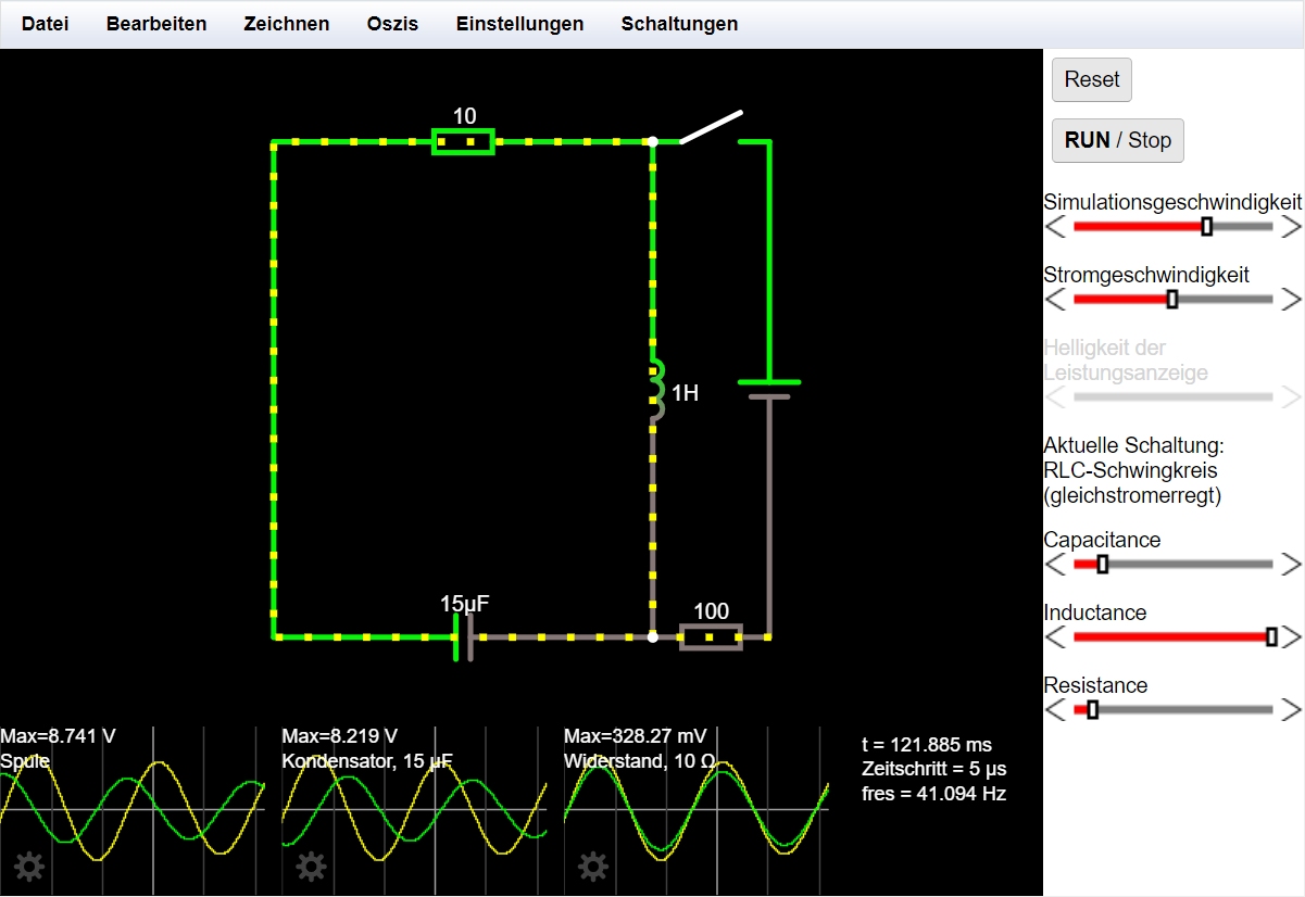 If you start the application, an example circuit appears. The circuit consists of different components and results in an oscillating circuit. Oscillators can also be displayed.
If the mouse is moved over the individual components of the circuit, information about the component is displayed in the text area at the bottom.
The circuit can be stopped or started from the beginning at any time. This is done with the Run/Stop or Reset button. With the help of the two sliders the simulation speed and the current speed can be controlled. I.e. I can make the simulation run faster or slower - or I can make the current run faster or slower. Both are set individually for individual controllers.
With a click on the resistor I can activate another slider, with which I can also then change the resistance. In the example circuit, there is a slider on the right for each component. So I can change the capacitance, the inductance and the resistance.
Menu bar
Under the menu item File, created files can be exported, local files and texts can be imported and circuits can be printed. To export the circuit, there are several possibilities. The own circuit can be saved locally as a text file. This text file can then be imported again at any time to continue working on the circuit. It is also possible to export the circuit as a link. In this case all information of the circuit will be inserted in a URL. This very long URL can also be shortened using the Shorten URL button. This link is not a permanent link, but rather a shortened form of the export/import function. Unfortunately, it is also not possible to work together with several people on one circuit.
Under Edit we find common functions such as copy and paste with a reference to the common key combinations.
Under Draw all available circuit elements are listed, which can be inserted into the circuits. This selection is also displayed when the right mouse button is pressed. All components, connections, inputs and outputs, logic gates, etc. can be selected to build the desired circuit and simulate it in real time.
In Oszis the oscilloscopes can be arranged and under Settings basic settings can be made. Here we can also switch between technical and physical current. Also, for better visualization, we can select under further settings whether or not voltages or powers should be displayed in color when the simulation is running.
Under Circuits, there are already completed circuits that can be selected. We see a large number of categorized and prefabricated example circuits that we can access and also adapt.
A new circuit
A new circuit can be created by selecting and adding new components via the Draw menu item or by right-clicking. You connect the components either by inserting connections or by dragging a component connection with the left mouse button. It is important that each component is selected and connected to the voltage source individually. It is not possible to drag a single connection across all resistors. If the mouse pointer is moved over the connections or the individual components, the individual information and sizes appear at the bottom of the text field. By right-clicking on the components, the resistance values can be changed. If one would like to look at the measurement with the oscilloscope, by a right click on a component its current and voltage course at the oscillogram are indicated. The display can be adjusted by right-clicking in the oscillogram (e.g. for power measurement, extreme values etc.). Several oscillograms are also possible. These can be stacked and/or combined in the menu at Oszis.
Conclusion
Falstad is not only suitable for creating and simulating your own circuits, but above all for applying and testing the extensive measurement and oscilloscope functions on the prefabricated circuits. The large amount of prefabricated circuits covers many topics of electrical engineering - from the basics like series and parallel circuits, capacitances and inductances to logic gates and conduction theory. The prefabricated circuits can be used to deal with specific electrical engineering topics on your own, or they can also be used very well as teaching aids.